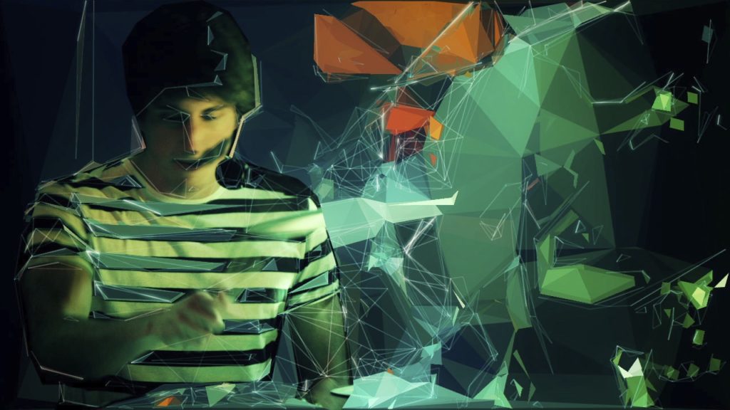
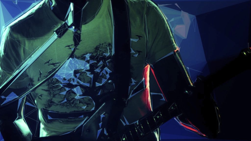
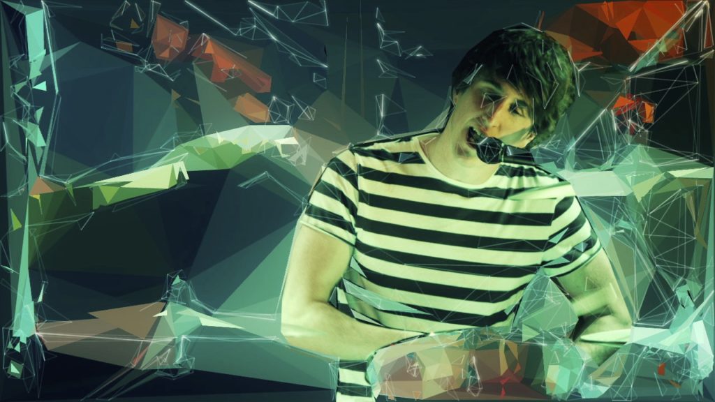
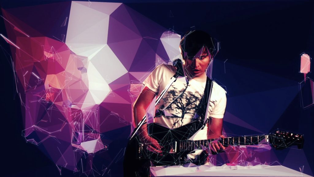
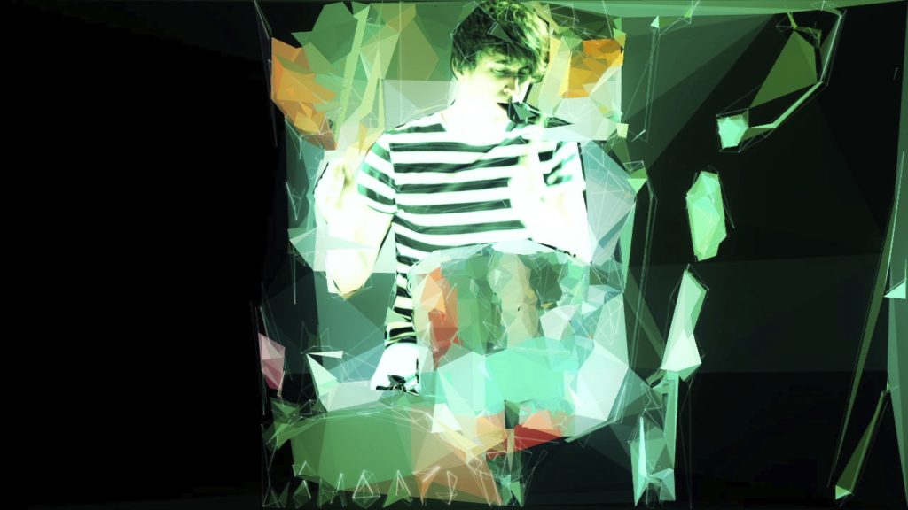
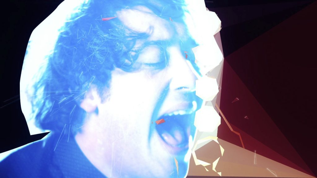
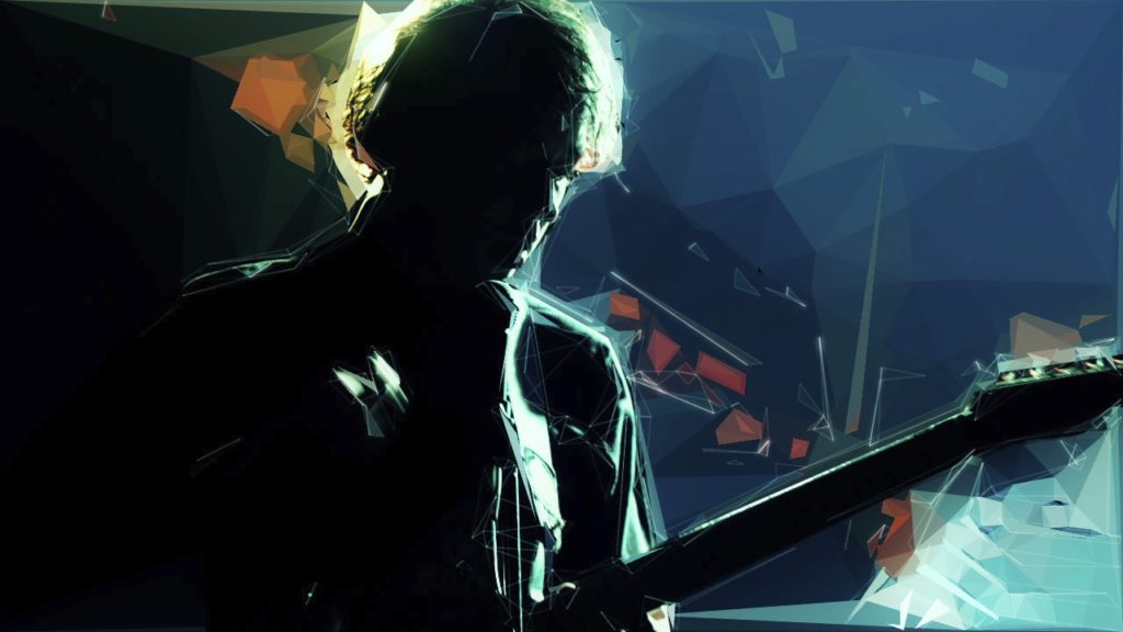
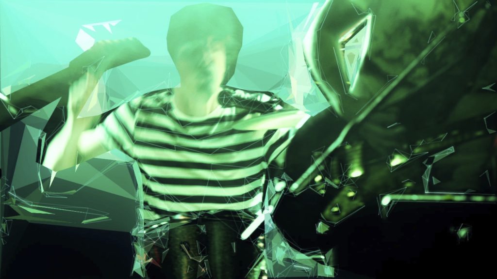
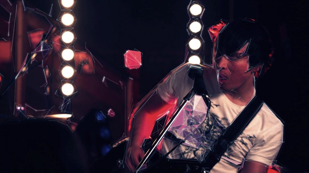
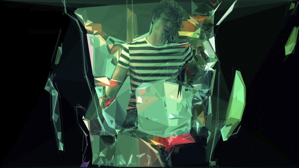
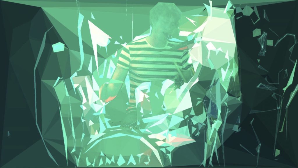
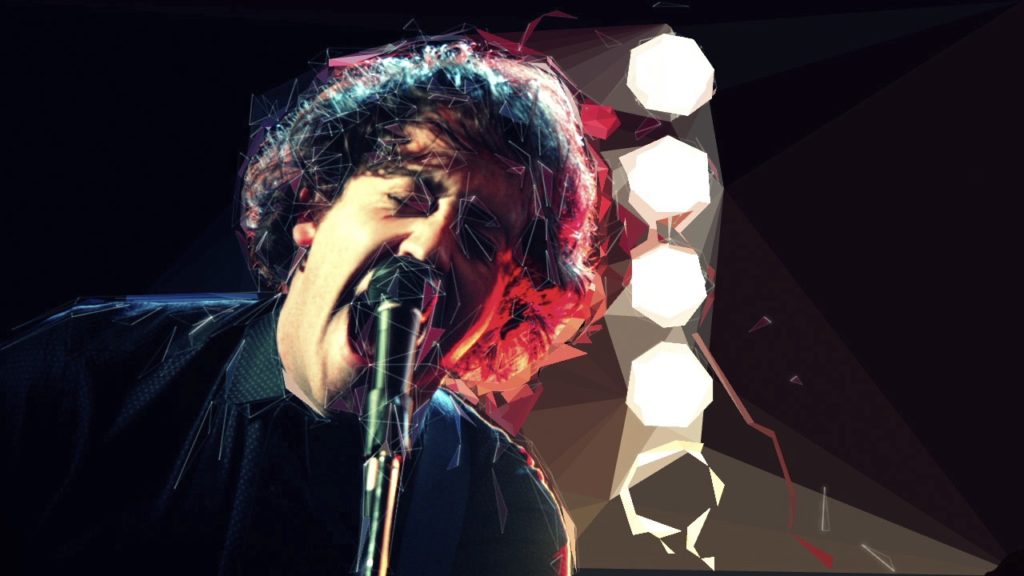
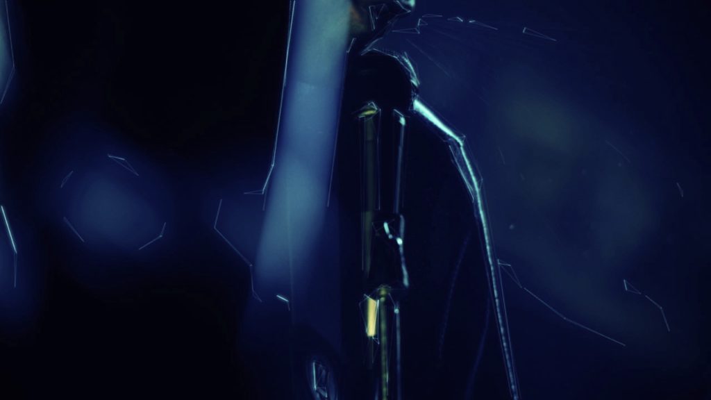
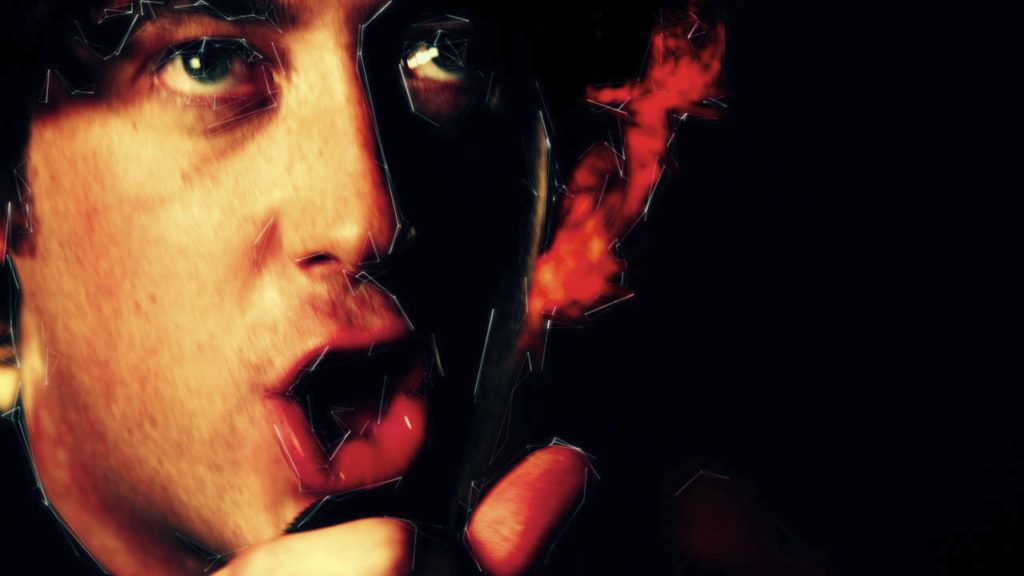
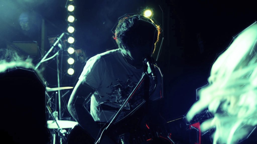
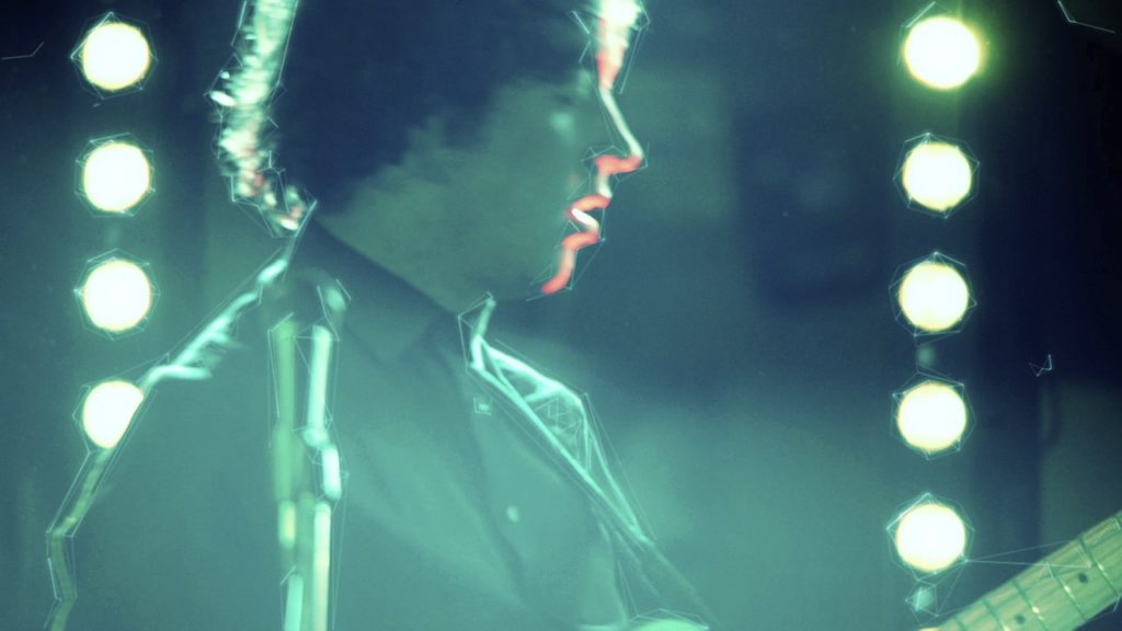
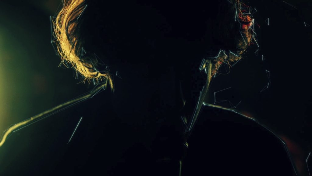
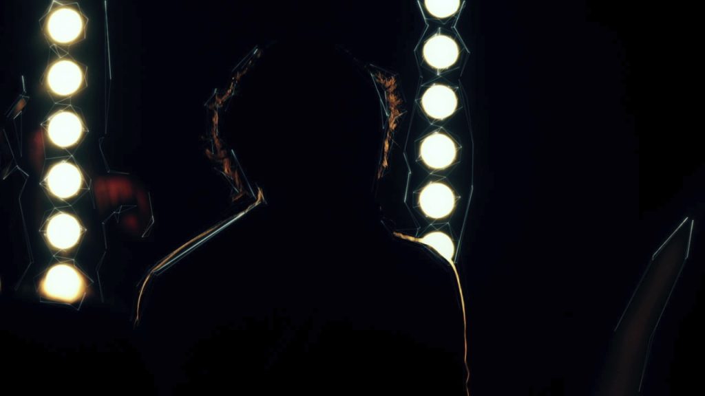
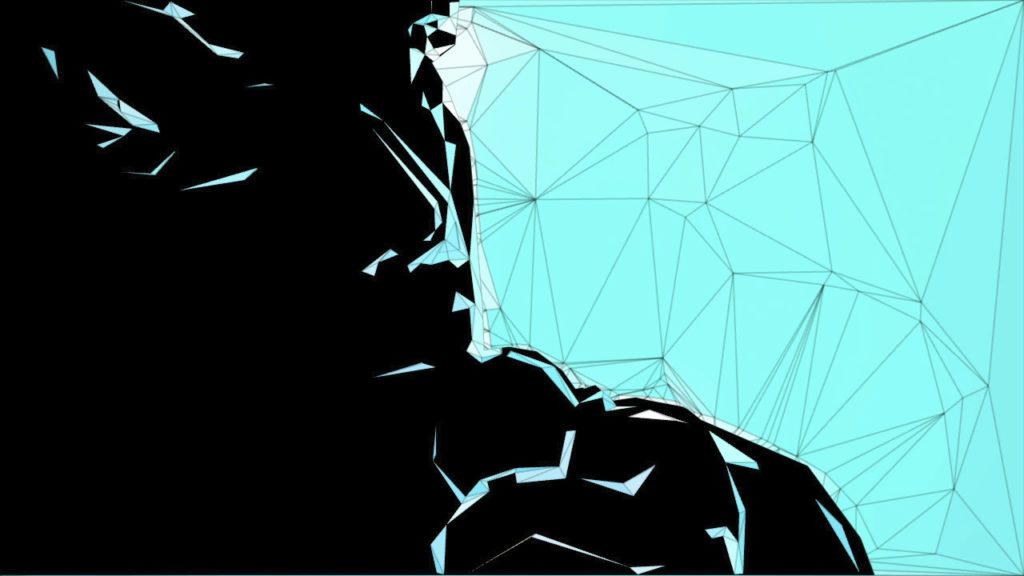
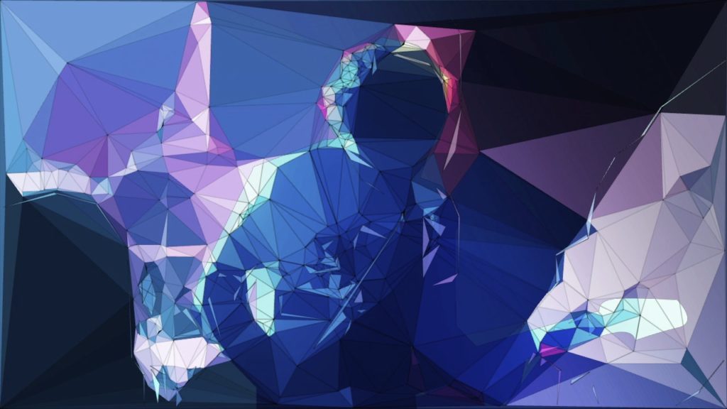
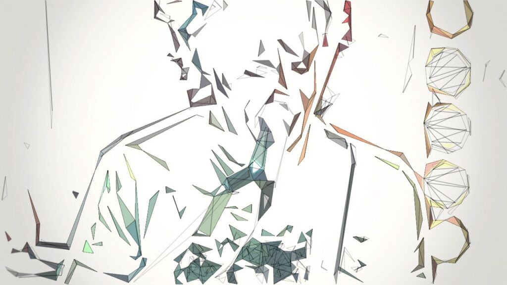
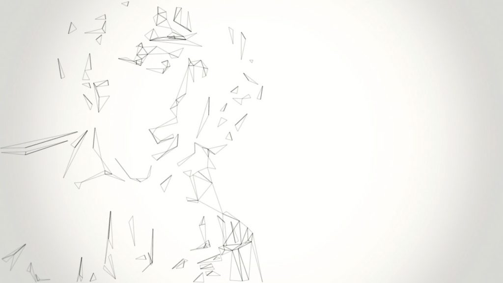
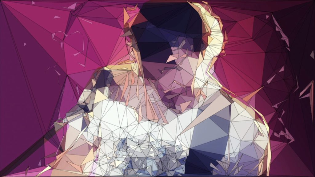
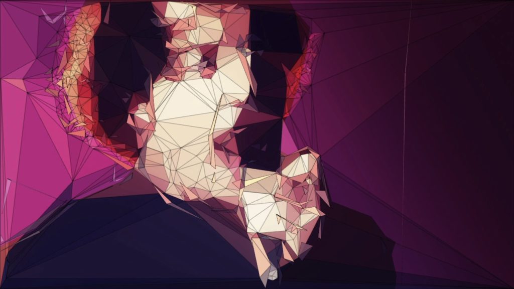
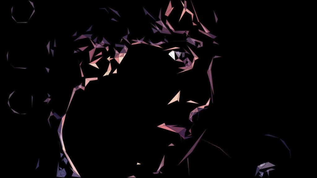
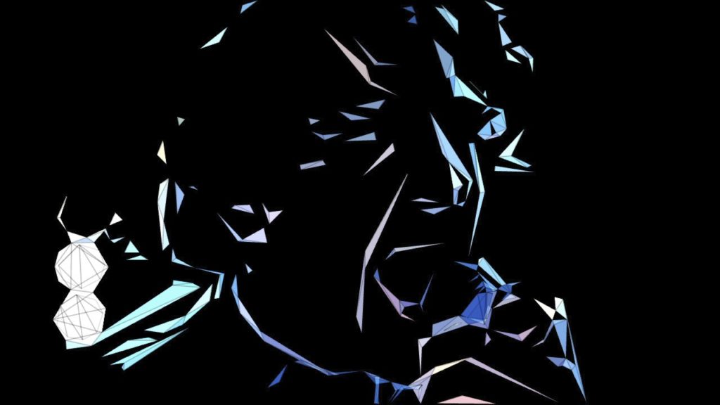
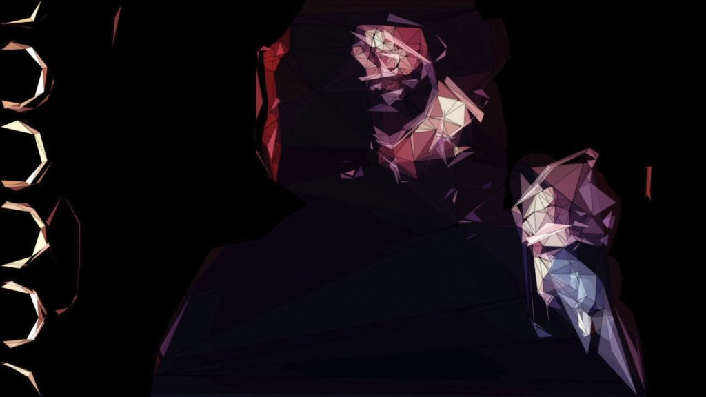
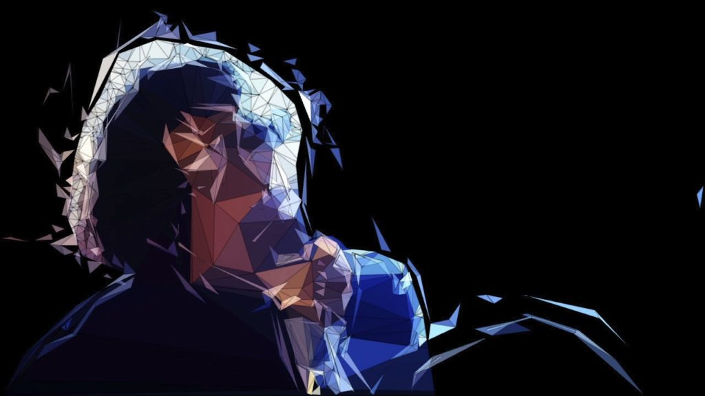
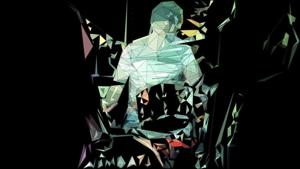
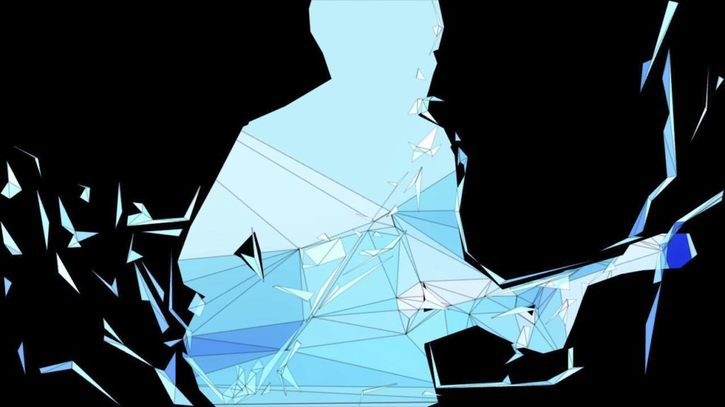
Music video for Wombats’ latest single “Techno Fan” made using custom software.
Wombats – Techno Fan (2010)
Credits & Acknowledgements
Director: Barney Steel (Found Collective)
Compositing/Post: Raoul Paulet, Barney Steel & James Medcraft
Visual and Software design & development: Memo Akten
made with openFrameworks
using opencv by Intel and Triangle library by Jonathan Shewchuk
Process
The raw video shots were broken down shot by shot and various layers were rotoscoped, separated (e.g. foreground, background, singer, drummer etc.) and rendered out as quicktime files. (This was all done in the traditional way with AfterEffects). Then each of these shots and layers were individually fed into my custom software. My software analyzes the video and based on the dozens of parameters outputs a new sequence (as a sequence of png’s). The analysis is done almost realtime (depending on input video size) and the user can play with the dozens of parameters in realtime, while the app is running and even while it is rendering the processed images to disk. So all the animations you see in the video, were ‘performed’ in realtime. No keyframes used. Lots of different ‘looks’ were created (presets) and applied to the different shots and layers. Each of these processed sequences were rendered to disk and re-composited and edited back together with Final Cut and AfterEffects to produce the final video.
Technical information
This isn’t meant as a tutorial, but a quick, high level overview of all the techniques used in the processing of the footage. There are a few main phases in the processing of the footage:
- analyze the footage and find some interesting points
- create triangles from those interesting points
- display those triangles
- save image sequence to disk
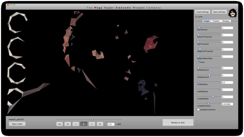
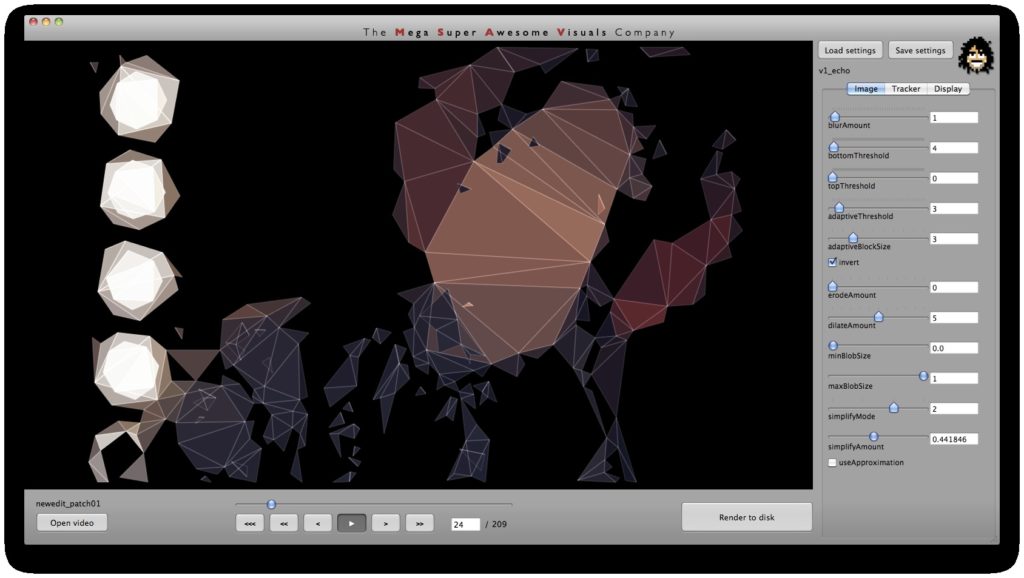
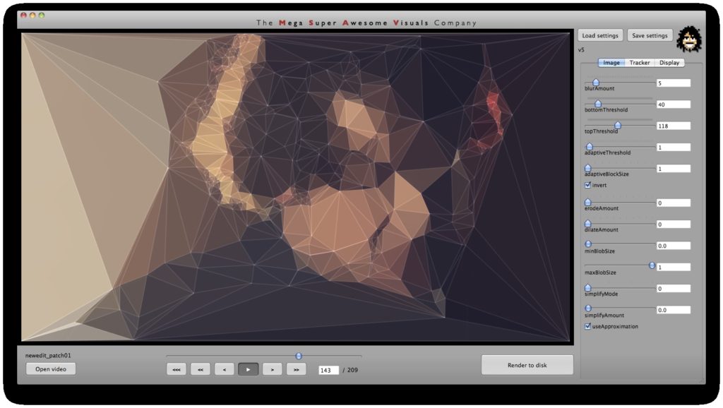
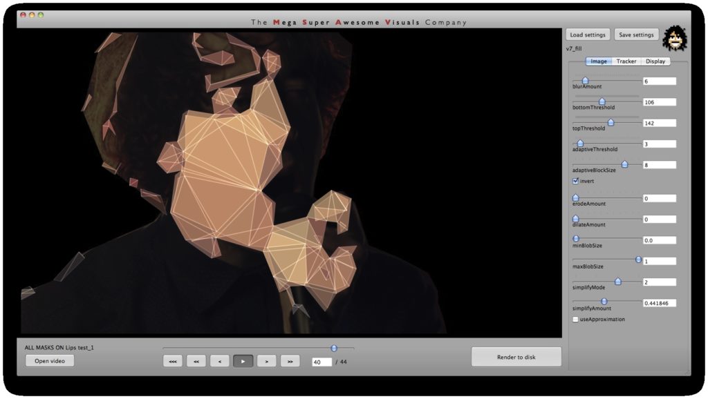
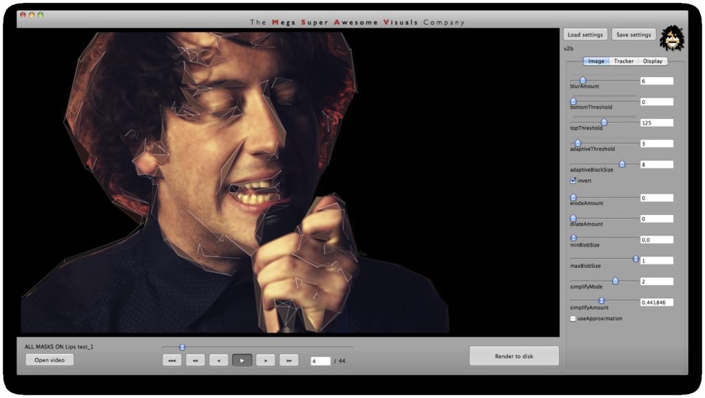
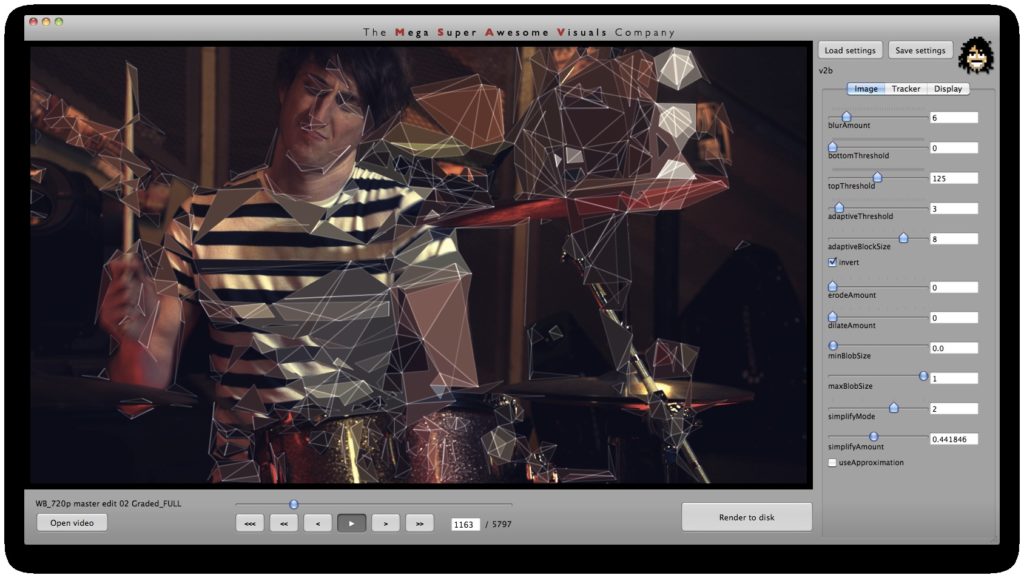
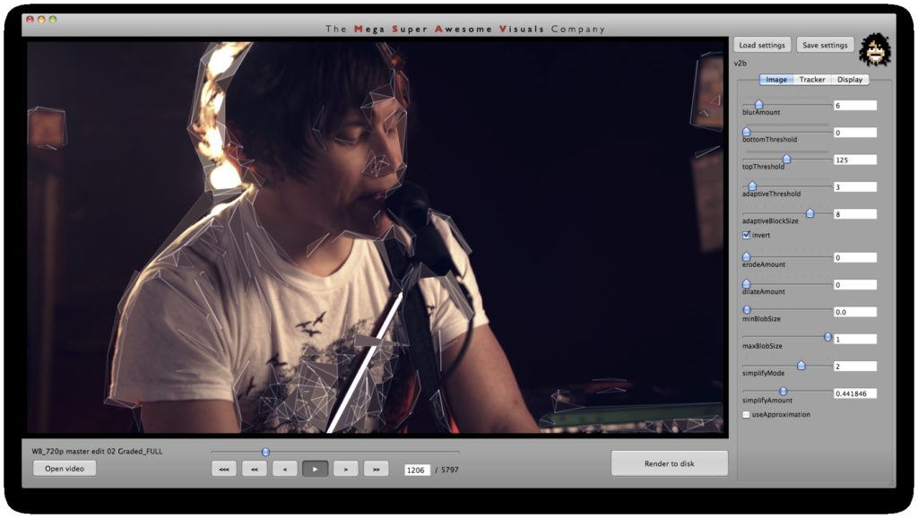
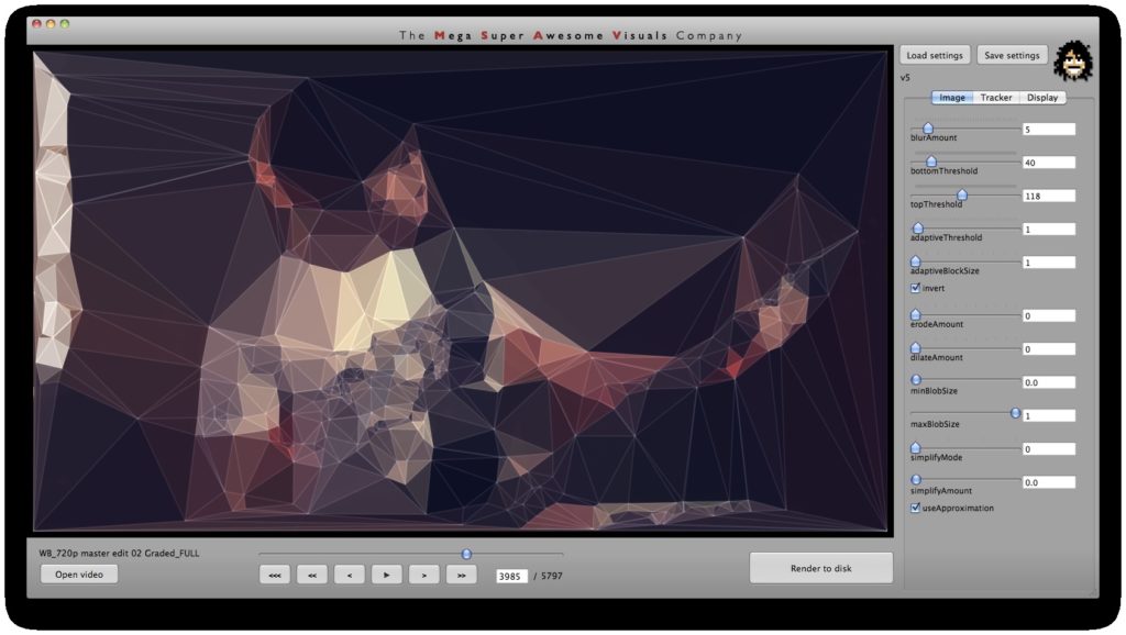
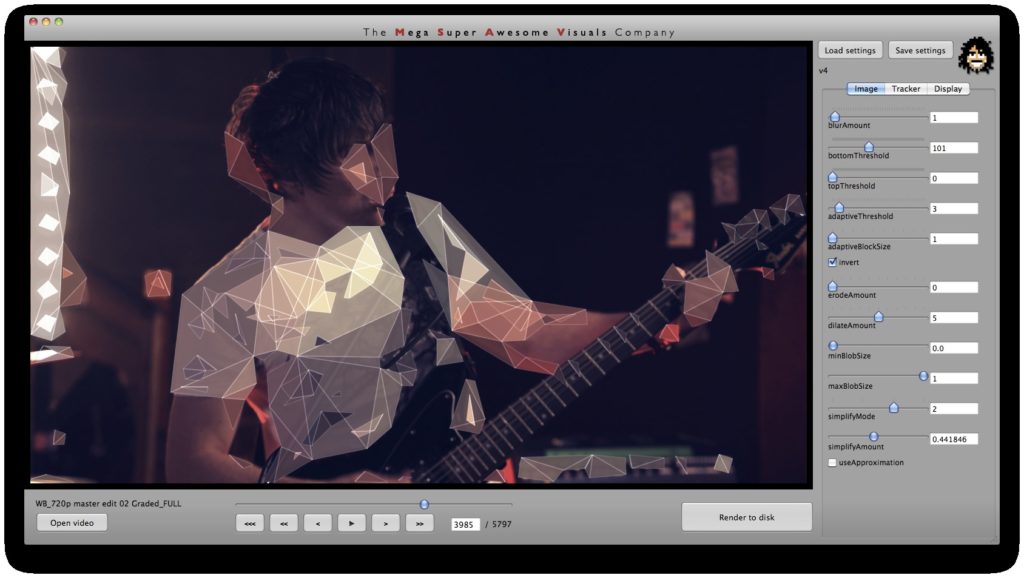
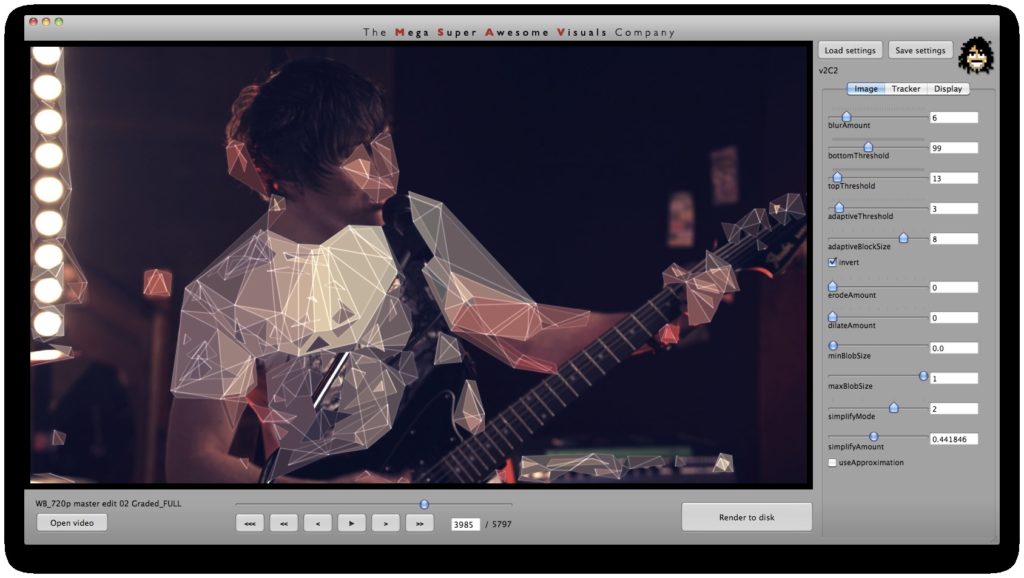
Phase #1 is where all the computer vision (opencv) stuff happens. I used a variety of techniques. As you can see from the GUI screenshots, the first step is a bit of pre-processing: blur (cvSmooth), bottom threshold (clamp anything under a certain brightness to black – cvThreshold), top threshold (clamp anything above a certain brightness to white – cvThreshold), adaptive threshold (apply a localized binary threshold, clamping to white or black depending on neighbours only – cvAdaptiveThreshold), erode (shrink or ‘thinnen’ bright pixels – cvErode), dilate (expand or ‘thicken’ bright pixels – cvDilate). Not all of these are always used, different shots and looks require different pre-processing.
Next, the first method of finding interesting points was ‘finding contours’ (cvFindContours) – or ‘finding blobs’ as it is also sometimes known as. This procedure basically allows you to finds the ‘edges’ in the image, and return them as a sequence of points – as opposed to applying say just a canny or laplacian edge detector, which will also find the edges, but will return a B&W image with a black background and white edges. The latter (canny, laplacian etc) finds the edges *visually* while the cvFindContours will go one step further and return the edge *data* in a computer readable way, i.e. an array of points, so you can parse through this array in your code and see where these edges are. (cvFindContours also returns other information regarding the ‘blobs’ like area, centroid etc but that is irrelevant for this application). Now that we have the edge data, we can triangulate it? No, because it’s way too dense – a coordinate for every pixel. So some simplification is in order. Again for this I used a number of techniques. A very crude method is just to omit every n’th point. Another method is to omit a point if the dot product of the vector leading up to that point from previous point, and the vector leading away from that point to the next point, is greater than a certain threshold (that threshold is the cosine of the minimum angle you desire). In english: omit a point if it is on a relatively straight line. OR: if we have points A, B and C. Omit point B if: (B-A) . (B-C) > cos(angle threshold). Another method is to resample along the edges at fixed distance intervals. For this I use my own MSA::Interpolator class ( http://msavisuals.com/msainterpolator). (I think there may have been a few more techniques, but I cannot remember as it’s been a while since I wrote this app!)
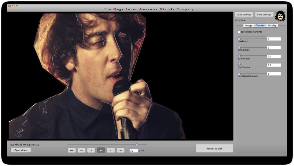
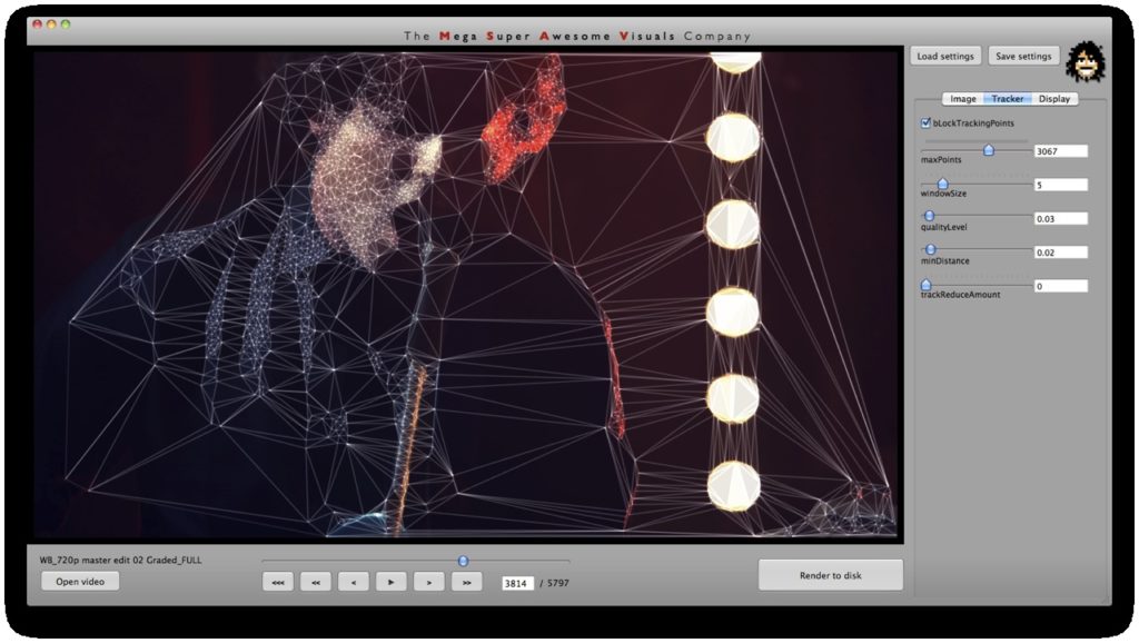
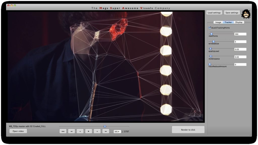
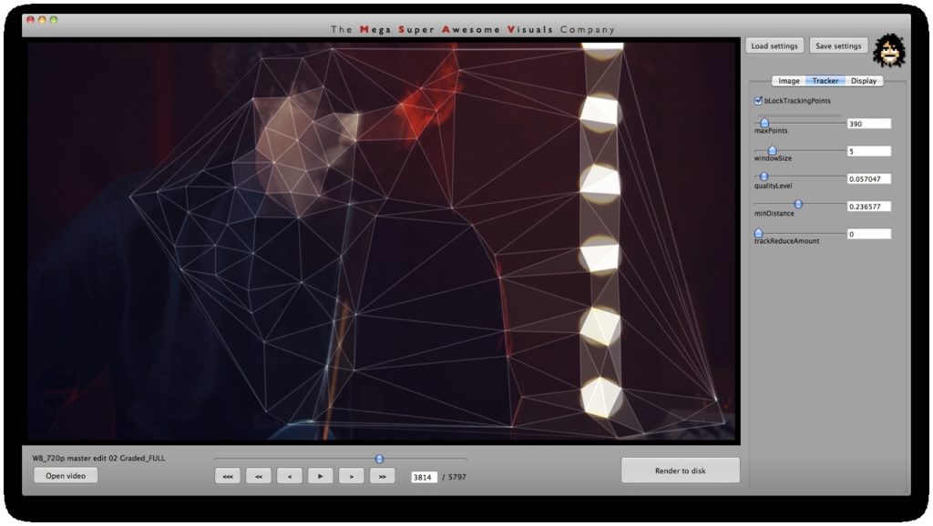
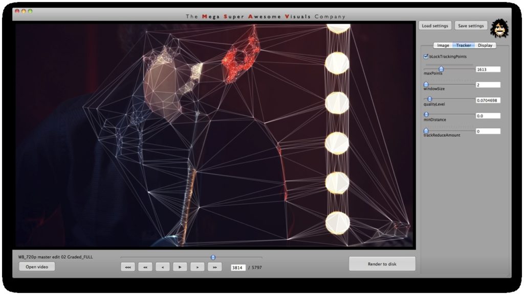
Independent to the cvFindContours point finding method, I also looked at using ‘corner detection’ (feature detection / feature extraction). For this I looked into three algorithms: Shi-Tomasi and Harris (both of which are implemented in opencv’s cvGoodFeaturesToTrack function) and SURF (using the OpenSURF library). Out of these three Shi-Tomasi gave the best visual results. I wanted a relatively large set of points, that would not flicker too much (given relatively low ‘tracking quality’). Harris was painfully slow, whereas SURF would just return too few features, adjusting the parameters to return a higher set of features just made the feature tracking too unstable. Once I had a set of points returned by the Shi-Tomasi (cvGoodFeaturesToTrack) I tracked these with a sparse Lucas Kanade Optical Flow (cvCalcOpticalFlowPyrLK) and omited any stray points. Again a few parameters to simplify, set thesholds etc.
Phase #2 is quite straightforward. I used “delaunay triangulation” (as many people have pointed out on twitter, flickr, vimeo). This is a process for creating triangles given a set of arbitrary points on a plane ( See http://en.wikipedia.org/wiki/Delaunay_triangulation for more info ). For this I used the ‘Triangle’ library by Jonathan Shewchuk, I just feed it the set of points I obtained from Phase #1, and it outputs a set of triangle data.
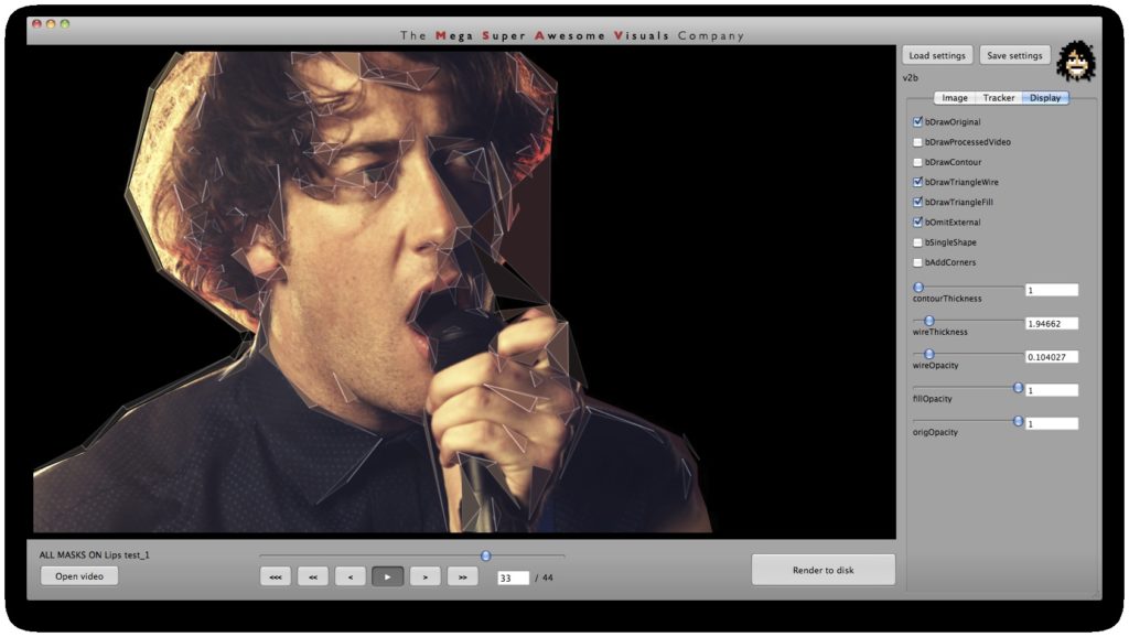
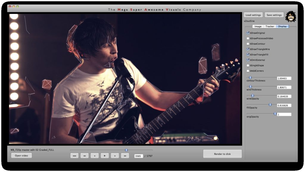
Phase #3 is also quite straightforward. As you can see from the GUI shots below, a bunch of options for triangle outline (wireframe) thickness and transparency, triangle fill transparency, original footage transparency etc. allowed customization of the final look. (Where colors for the triangles were picked as the average color in the original footage underneath that triangle). Also a few more display options on how to join together the triangulation, pin to the corners etc.
Phase #4 The app allowed scrubbing, pausing and playback of the video while processing in (almost) realtime (it could have been realtime if optimizations were pushed, but it didn’t need to be, so I didn’t bother). The processed images were always output to the screen (so you can see what you’re doing), but also optionally written to disk as the video was playing and new frames were processed. This allowed us to play with the parameters and adjust while the video was playing and being saved to disk – i.e. animate the parameters in realtime and play it like a visual instrument.

